SNT BLOG

BLOG: An Introduction to Grab Sampling
Grab sampling, also known as spot sampling, laboratory sampling, field sampling, or sometimes just sampling—involves the collection of a sample fluid in a pipeline, tank, or system. The sample is then analyzed to help operators validate process conditions, evaluate products for environmental emissions according to local regulations, and detect whether the product is up to customer specifications.
Importantly, grab sampling is a process that must be performed in accordance with established best practices and with reliable equipment. If performed incorrectly, the integrity of the sample can be compromised, offering operators an inaccurate analysis of their processes that may negatively influence decision-making. This white paper will detail grab sampling best practices for both gaseous and liquid fluid system media, the characteristics of well-designed and easily operable grab sampling systems, and how to reliably achieve grab sampling accuracy. Download Whitepaper Here
BLOG: The Making of a Swagelok Tube Fitting
Swagelok is a premium manufacturer of components around the globe. Our best-known product is the Swagelok tube fitting, so we'd like to give you a closer look at the making of this component.
Like any other great invention, this component started with a great idea. Swagelok engineers come from the U.S. Military and respected international universities. They hail from top partners in industry and manufacturers around the world. They bring their knowledge and experience to the resources Swagelok has developed for constant innovation.
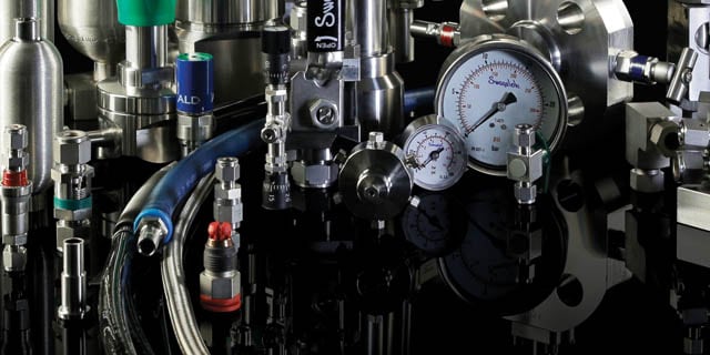
Swagelok introduced the original flareless, mechanical grip-type, two-ferrule tube fitting in 1947. We have continued to improve our proprietary design ever since. Swagelok tube fittings have a grip-type design that uses a unique “hinging and colleting” action to achieve prime performance in three key areas: tube grip, gas seal, and vibration resistance. The unique leak-tight design of this component reflects the importance of innovation, integrity, and quality that define Swagelok.
Over time, Swagelok has added a wide range of other components, each made with care and attention to detail. Gathering regular feedback from our customers, Swagelok has expanded our innovation, technology, and field engineering teams, invested in an in-house makerspace for peer collaboration, and developed an online crowdsourcing tool to boost the ability to collaborate and to speed the identification of viable solutions to industry challenges.

How to Reduce Your Maintenance Spend by Improving Gas Distribution
Mark Welch, Regional Field Engineer, Swagelok London
For a maintenance technician, servicing a gas pressure control panel can often be like solving a puzzle.
Confusing or unintuitive tube or pipe layouts may block easy access to components requiring attention. Several threaded connections might require disassembly for service, followed by remaking upon completion of the task. An unlabeled valve or regulator may leave the technician uncertain how to choose a replacement.
All of this can be time-consuming, labor intensive, and thus, costly work—but it is all necessary for chemical plants or laboratories that require widespread distribution of various gases to conduct their operations. System reliability is imperative. Operations can be dramatically slowed down or even stopped if gas is not available when and where it is needed.
Optimized Pressure Panel Design = More Intuitive Operation and Maintenance
Traditionally, gas panel design has been far from intuitive. Componentry that often requires regular service—safety relief valves and regulators being two of the most common examples—might be hidden behind an enclosure or blocked behind tubing that must be disassembled in order to gain access. Some of these design choices may also make it difficult for a technician to interpret how the panel operates, inhibiting his or her ability to properly service the panel. All of this can lengthen the amount of time required to complete maintenance.Operations can be dramatically slowed down or even stopped if gas is not available when andwhere it is needed.
Consider also that while service is being performed, the supply of gas is cut off to its point of use. This kind of downtime means that production or testing cannot continue until the task is complete and the panel has been reassembled and turned back on.
Newer gas panels featuring an optimized design can alleviate some of these maintainability concerns. Look for panels that feature clear visibility and labeling of critical components like regulators and pressure valves. Modular designs allow a technician to swap out components more easily via tube fitting connections so the entire panel itself can remain in place while being serviced. Your gas panel supplier should also take your specific needs into consideration and offer a configuration that works best for your operation.
Stronger Connections = Fewer Leaks
In addition to being easier to maintain and reassemble than threaded connections, tube fittings can also form a more robust connection that can eliminate small, unnoticed leaks that may add up to considerable costs over time.
Consider nitrogen, a utility gas used for dozens of different purposes in laboratories, refineries, and other facilities. A small nitrogen leak may not be considered an immediate safety hazard, but the escaping gas can be expensive over a longer amount of time. Numerous small nitrogen leaks throughout a system can result in the operator paying for gas that is wasted as it escapes the system. For more expensive gases, these leaks are even more important to identify and eliminate.
Checking for small leaks throughout a gas distribution system, however, is not always a top priority for a facility operator. There are dozens of other priorities that might take precedence on a given day. Selecting high-quality tube fittings at different connections throughout a gas distribution system can be beneficial, offering reliable, leak-tight performance for the long term. Better yet, working with a components supplier who can offer evaluation services and actionable insights to achieve more efficient gas distribution can offer even bigger benefits.
Quality Parts = Fewer Interruptions
Gas panels and systems made from high-quality individual components can help drive down maintenance-related labor costs, as well.
For example, regulators—the devices that reduce gas pressure in gas from its source for use at the next step in the system—are often the subject of scheduled replacement. Conventional wisdom states that most regulators should be replaced every five years, depending on the build quality. It is also common practice for regulators to be provided by your gas supplier. Following a schedule like this is not typically questioned. After all, swapping out a regulator rated for five years of use when necessary should help prevent performance issues, though doing so requires downtime and interrupted production.
However, not all available regulators are created equal. Higher-quality pressure regulators that have been tested and rated for millions of cycles can last the lifetime of your gas distribution system, functionally eliminating the need for periodic replacement and the associated labor required to do so. Regulators designed to a higher standard can help you keep producing with fewer interruptions (and less associated downtime) while offering peace of mind regarding your system’s performance and safety.
For many labs, refineries, and other facilities, gas distribution and delivery systems represent a significant opportunity to achieve greater efficiencies and maintenance-related cost savings. To learn more about the benefits that modern gas panels provide, and how advisors who specialize in gas distribution can help you reduce your operating costs, start a conversation with us today.
Why High-Performing Fluid Systems Matter in New Semiconductor Fab Construction
Masroor Malik, Market Manager, Semiconductor
When building a new semiconductor fabrication facility (or “fab”), there are many considerations, including speed to market, material and installation standardization, and cost. Many estimates put the cost of building a new fab over $1 billion. Values as high as $3 – 4 billion are not uncommon, and some of the largest fabs may soar past $10 billion.
Cleanrooms and the expensive microchip fabrication equipment make up the bulk of these expenses, but total cost of ownership can be highly influenced by other systems and equipment throughout the facility.

Fluid management systems, which function essentially as the fab’s circulatory system by transporting liquids and gases where needed throughout the facility, are one such example. When approaching new semiconductor fab construction, there is significant opportunity to contribute to the fab’s short- and long-term profitability by specifying high-quality fluid system components and assemblies, and by working closely with fluid system suppliers during the front-end engineering and design (FEED) stage of development.
Here are five ways taking a careful approach to designing and installing fluid systems can contribute to a more profitable fab:
#1. Faster, Leak-Tight Installation
New fab construction is typically indicative of new production technology and/or capacity expansion, making speed to market a primary objective to stay ahead of the competition. Semiconductor manufacturing and production is expected to begin as soon as possible—in some cases, possibly before the entire facility is finished.
Put simply, there is no time to waste. But designing and constructing complex fluid systems and routing them throughout the fab can be a time-consuming process, involving a significant amount of labor and expertise to properly bend the appropriate tubing, install critical components, and ensure total system integrity. This process can be especially difficult if contractors and installers do not have the proper knowledge or training to assemble highly reliable, leak-tight systems.
Custom engineered and prefabricated fluid system assemblies can help eliminate installation issues during construction and remove a significant amount of labor involved in assembling complex subsystems. Look for a supplier that will work to understand your needs and that can provide a complete, easy-to-install assembly made with high-quality components. The time saved can help your fab become fully operational that much faster, enabling full-scale semiconductor production to begin.
#2. More Efficient Planning and Design
Fab fluid systems are comprised of a variety of components, including tube fittings, valves, regulators, hoses, and tubing. Proper system planning, efficient design, effective tube routing, and other installation best practices can help contribute to a system that is up and running faster and will be able to perform reliably for the facility’s lifetime.
For example, a subsystem that requires a complex series of tubing directional changes can pose a challenge for in-house designers or installers. Working with a supplier that provides a complete subassembly can once again be a valuable asset, as tube bends will have been performed offsite. The complete subsystem will be ready to install and leak-tight upon delivery.
Elsewhere, an efficiently designed fluid system may incorporate numerous tube bends where additional fittings may have been otherwise used. Reducing unnecessary connection points can help save the fab builder money on extra parts, and also by eliminating potential leak points. Manufacturers can drive down short-term costs during construction, as well as the total cost of ownership over the life of the facility, by specifying higher-quality fluid system components and relying on fluid system design and service experts for support where needed.
#3. Reduced Total Lifecycle Costs
Once the fab is in production, operational efficiency and maximized throughput are priorities. Any downtime resulting from a fluid system failure can mean significant financial loss for every hour production must be shut down. Sourcing high-quality components and assemblies at the start of the process can be help eliminate maintenance, repair, and operations (MRO) requirements over the life of the facility.
For example, fabs use powerful chillers to maintain optimal temperature stability in manufacturing processes. However, if a coolant transport hose is not outfitted with the proper insulation, temperatures in the tool chamber may fluctuate, presenting a challenge to maximum production output. Selecting the right type of insulation in hoses from the outset can help reduce the likelihood of any issues, including condensation, which is common in a fab environment.
Choosing high-quality components and well-designed systems at the outset of construction will allow for easier and less time-consuming MRO activities. Additionally, fewer necessary component and application replacements will be required over time. The savings and reduced downtime achieved can help the facility remain more productive—and more profitable—for the long-term.
#4. Standardized, Global Quality
Fab owners must often consider how to best replicate standards and processes across multiple global locations to ensure maximum production viability and maintain quality requirements.
Standardized fluid system components and applications throughout all facilities can be beneficial. Consistent systems will contribute to easier maintenance, better continuity of installation techniques, and overall safety of production operations. Finding suppliers with global construction services, including worldwide supply chain capabilities and local support can help fab builders reduce overall procurement and spending costs. Working with these organizations across facilities can lead to efficiencies and design choices that yield sizable profitability improvements worldwide.
#5. Increased Productivity and Throughput Yield
Once a fab is commissioned and operational, high-quality fluid systems that eliminate the need for ongoing maintenance and downtime can contribute to higher levels of productivity and viable chip yield by providing millions of uninterrupted, ultra-high purity-level clean production cycles. Production reliability can help a producer gain or maintain their edge in this highly competitive industry.
When commissioning a new fab, minimizing upfront component costs while sticking to ambitious construction timelines are among the most important goals for a builder. But as we have seen, sourcing higher-quality parts, components, and subassemblies for critical fluid systems throughout the fab can contribute to numerous benefits and overall lower cost of ownership for the lifetime of the facility.
Interested in learning more? Swagelok has helped semiconductor producers design and build fluid systems around the world. Get in touch with our teams to find out how our design and assembly services can help with the construction of your next fab.
 Controlling Costs and Reducing Errors in Liquid Grab Sampling
Karim Mahraz, Product Manager, Analytical Instrumentation, Swagelok
Grab sampling plays a critical role in accurate, profitable industrial processes. The practice can help validate process conditions, ensure end products are up to specification, and provide the information necessary to evaluate environmental emissions. However, grab sampling—also called spot sampling, laboratory sampling, field sampling, or closed-loop sampling—can be complex and challenging to execute correctly. Even small errors can negatively impact sample representativeness and production, driving up operating costs.
It is important that individual operators and technicians are equipped with the right skills to perform grab sampling correctly. There are several operational strategies that can help promote consistent, accurate, and cost-effective sampling at every location. Read on to discover three key methods to optimize liquid sampling in your plant.
 Use Sample Bottles Wherever Appropriate.
Choosing between sample cylinders or bottles is one of the first decisions to be made for liquid grab sampling and is largely dictated by the type of sample being collected.
Sample volatility and toxicity may necessitate the use of sample cylinders. Metal cylinders can help maintain precise pressure and temperature levels that may be required to keep a volatile liquid from fractionating or otherwise misrepresenting true process conditions. Cylinders are required in gas sampling systems, and are highly effective at protecting technicians and the environment from potentially toxic fumes or emissions.
However, sampling cylinders are significantly more expensive than glass or polyethylene chemical sample bottles, which can be effective for collecting nonvolatile, nontoxic liquids. Generally, these are large-molecule liquids with high boiling points that do not flow or ignite easily, ranging from bitumen used in roads and roofing to diesel fuels.
Basic Rules for Sampling
Grab sampling helps validate process conditions and ensure a quality end product. Keep these rules in mind for your grab sampling process:
- The sample must represent the process. Use probes to draw samples from the middle of the process pipe, and avoid phase changes during sample transportation.
- The sample must be timely. Minimizing transport time from the draw point to the laboratory helps ensure process conditions are accurately represented.
- The sample must be pure. Avoid dead legs upstream of the sample container, and allow for adequate purging and flushing of the sampling system to minimize the potential for contamination.
If your application allows for bottle collection, using them instead of cylinders can be an effective way to optimize grab sampling costs. Some bottle options include a self-sealing septum cap which can help prevent accident spillage or overfilling. Bottles also provide the opportunity for immediate visual analysis, helping technicians provide quick feedback on the sample stream.
Maintain a Standard Sampling Process.
More extensive industrial fluid systems may require multiple sampling points. If this is required, it can be helpful to maintain consistent grab sampling processes and panels at each point to reduce the likelihood of error.
Consistency at multiple sampling points grants plant operators greater assurance that proper procedures are being followed at every point. Additionally, it offers convenience for the technicians drawing samples—consistency means they will not have to follow a different set of considerations or operations at unique points throughout the system. This can be helpful especially for technicians with varying skill levels and can make training easier.
To achieve this consistency, system engineers can specify a certain type of grab sampling panel in their designs. Beyond the scope of just one plant, global organizations can achieve grab sampling consistency by specifying a certain panel or certain liquid sampling equipment across all sites. This helps ensure that differing regional preferences will not influence the sampling process, and that sound procedures are being followed throughout the organization’s global footprint.
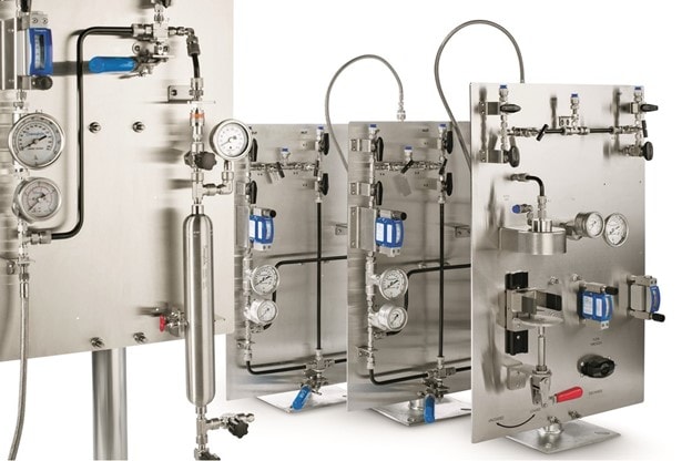
Choose Well-Designed Sampling Panels.
Advancements in grab sampling systems have helped make the process simpler, safer, and more repeatable. For plants that have been following the same grab sampling process for years, it is worth considering improvements that could be made to drive greater sampling efficiency and accuracy.

Elsewhere, some new sampling panels have been designed with heightened user convenience in mind. Obtaining samples, venting, flushing, and purging are all accomplished by operating a series of different valves. Today, geared valve assemblies are available that are designed to activate the necessary valves in the proper sequence, helping the operator more easily control fluid routing through the panel. Additionally, technicians can more easily isolate gauges when performing maintenance. Geared valve assemblies also help minimize the chance of operator error by preventing valves from being activated out of sequence. valves from being activated out of sequence.
Grab sampling is a critical process for chemical and petrochemical refining, oil and gas production, and a variety of other process-driven industries, and specifying modern grab sampling panels throughout a facility or facilities is one way to help control costs and minimize errors. Additionally, working with a supplier who can help identify your system’s unique needs can lead to additional benefits.
Interested in learning more about how to optimize your grab sampling processes? Explore our solutions for grab sampling, and contact our team to discover how our team can help.

How to Improve Your Maintenance Program with Valve and Hose Tags
Imagine you are a technician performing maintenance on an industrial fluid system. You receive a new work order—several hoses require attention in a certain application in the system.
You take a look at the relevant application, and you see upward of a dozen hoses carrying and valves controlling the flow of critical fluids from one place to the next, none of which are easily identifiable on sight. Some questions immediately arise:
- What types of fluids or gases are being transferred?
- Are those fluids at high pressures or temperatures?
- Are they potentially hazardous?
- How long has each hose been in service?
- What materials are the hoses made of—what sort of replacement is necessary?
Determining the answers to these questions may involve referencing system schematics and can require significant time and effort on your part. All the while, the application has been shut off to perform the maintenance work, creating downtime and lost profit potential.
This situation is emblematic of many fluid system applications. There is an easy solution, however: thorough tagging for all—even seemingly less critical—parts of your fluid system. We asked two Swagelok specialists to offer their unique perspectives on how tags can be leveraged for better outcomes and how you can work with your manufacturer to ensure the right information is included. Read on to learn the benefits you can achieve by adding tags to your hoses, valves, and other components, including more effective maintenance and improved system uptime.
A More Proactive Approach to Maintenance
Paul Stevens, field engineer, Swagelok Manchester, says:
“Most plants tag major fluid system components—items like pumps or other key components to system operation. But not all production facilities tag every item on site. Simple hose tags and valve tags can be beneficial, helping eliminate identification headaches for the maintenance team.
For example: If a maintenance technician is performing a routine checkup on a system involving multiple hoses, a good hose identification tagging system would let that tech know when each hose was last installed, its core material, what fluid it is carrying, and other critical information. Without tags, it’s a guessing game. A tech might deem each hose to be in good working condition because there are no obvious, visible issues.
However, there are often time-specific maintenance requirements for many regulators, hoses, and valves that a simple visual check might not identify. Leaving a hose or valve operating beyond its intended life could lead to an issue that maintenance teams are then responding to reactively. With tags, they can be more proactive by replacing a component before it fails.
Additionally, tagging can help identify specific issues or faults that have developed on site. By tagging and recording issues this way, there is both a record and a specific location that the maintenance team can use to quickly identify the item that needs to be replaced or worked upon.”
At a minimum, tags should be used to identify the part number, date of manufacture, and the trace identification number, which ties the product to the original order. System media, operating pressure, and temperature are also valuable information that can be included.
Greater Efficiency With the Right Information
Aaron Lindrose, Hose Technical Service, Swagelok, says:
“Tags are a cost-effective way to improve efficiency by allowing easy identification of products, and are effective in establishing preventive maintenance programs, but only when labeled with the right information.
At a minimum, tags should be used to identify the part number, date of manufacture, and the trace identification number, which ties the product to the original order. System media, operating pressure, and temperature are also valuable information that can be included. Some hose manufacturers will include this information as standard on every hose, and will offer several different tag styles to suit the individual plant’s needs, or those of their industry. For example, Swagelok offers several styles of tags that correspond to the markets we serve, from simple metal tags to color-coded tags that wrap around the hose near the end connection. We are also happy to help our customers solve all sorts of hose related challenges.
The tag type and size will dictate the amount of data that we are able to etch on the tag. The maximum amount of data possible is five lines of text and 25 characters per line, including spaces. If desired, tags can be encapsulated in silicone to minimize entrapment areas and facilitate ease of cleaning the hose exterior. With this information readily available, maintenance technicians can more easily and efficiently service their systems.”
Now, imagine our original scenario once again. You receive a work order for maintenance on an application involving several industrial hoses. This time, the answers to all your questions—about system media, operating pressure, original date of installation—are readily available and neatly contained within a tagging system. The job can be completed more easily and efficiently, and your system is back up and running much faster.
Interested in learning more about how to develop a more effective tagging system in your facility? Our specialists would be happy to help. Get in touch with your local authorized Swagelok sales and service center to find out how you can expedite maintenance, improve system safety, and minimize downtime today
2020 In Review: What You Wanted to Know in an Unprecedented Year
Have you ever wondered how we come up with topics for Swagelok Reference Point each week?
The formula is simple: Our blogs are based on the conversations our global team has with customers every day. In 2020—an unprecedented year by any measure—our most popular articles reflected some of the most frequent and pressing challenges we heard from you. In our effort to answer your questions, we covered everything from green transportation to grab sampling, from gauge performance to virtual fluid system evaluations.
We recruited our experienced professionals from around the world to help answer your questions and proposed solutions. We crunched the numbers; here are our most popular blog posts of the year, and your questions that brought them to life:

“I’m limiting visitors to my facility because of the pandemic—but I still need advice on and assessments of fluid system performance. Can you help?”
As the COVID-19 pandemic forced industries everywhere to implement social distancing protocols and limit travel and visitation from outsiders, our teams got to work determining how we could provide the same level of practical knowledge and service.
In this account from our global field engineering team, we explored how virtual “on-site” visits utilizing industrial augmented reality can deliver safer and more efficient operation of your critical fluid and sampling systems.
Read: “Industrial Virtual Visits: A New Form of “On-Site Experience”

“What is the easiest way to tell if one of my gauges is broken?”
Pressure gauges are critical parts of fluid systems across industries. The visual indication of system pressure they provide lets you know whether everything is operating within the desired range or if a problem is imminent.
How can you prevent pressure gauge failure? There are a few visual indicators technicians and operators can quickly look for to identify and replace a gauge before it fails. We broke down the five signs of pending failure in this blog.
Read: “How Can You Tell a Gauge is Broken or May Fail?”
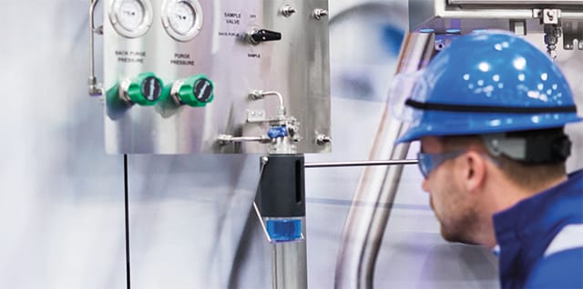
"How can I be sure that my grab sampling systems are operating as efficiently as possible?”
Grab sampling is one of the most effective ways to ensure that process fluids and end-use products are up to specification. The Swagelok field engineering team inspects a variety of liquid and gas grab sampling systems and setups while working in the field—many of which are optimized and operating properly, but many are not. In this article, we outlined some of the most common grab sampling deficiencies we see and how to fix them.
Read: “How to Fix Common Grab Sampling Deficiencies”

“How can I design an optimized hydrogen fuel system?”
Some special considerations must be made when selecting materials and components for use in fuel systems on hydrogen fuel cell vehicles. Specifically, designers need to account for hydrogen embrittlement, intense pressures, and other factors that are unique to hydrogen-based transportation. We explain how to obtain the highest levels of performance with mechanical grip fittings designed for hydrogen containment, including how to choose the right alloy formulations that resist hydrogen embrittlement and corrosion, in this popular post.
Read: “Optimizing Component Selection for Hydrogen Vehicles”

“How do I ensure ultrahigh purity in my atomic layer deposition process?”
In semiconductor production, the precision of gas dosing during the atomic layer deposition (ALD) process can have a major impact on total yield during the chip-manufacturing process. Ultrahigh-purity (UHP) valves used in ALD processes are more advanced than valves commonly found in general industrial applications, but lately, the semiconductor manufacturers we work with have been asking for even higher performance when it comes to factors like thermal stability and flow capacity. In this blog, we explore how new valve technology can deliver the performance semiconductor manufacturers are seeking.
Read: “One New Valve. Three Reasons It Could Change Semiconductor Manufacturing.”
We look forward to providing you the answers to your most pressing questions throughout 2021 and beyond.
Fiber Optics Equipment Manufacturer Increases Efficiency with Customized Solutions
December 8, 2020
Rosendahl Nextrom is a leading supplier of production equipment technologies for optical fibers and fiber optical cables for the telecommunications industry. Its core competencies include providing solutions used in the making of optical glass preforms, fiber drawing and coating, ribbon-making, proof-testing, and fiber optic cable—all of which require cleanliness and purity of gases to ensure the quality and reliability of end products.
To keep up with the rapid pace of innovation and change in the industry, Rosendahl Nextrom turned to Swagelok Helsinki for customized fluid system solutions that would help them prevent leaks, ensure product quality and consistency, and streamline operations.
Hear how Rosendahl Nextrom was able to improve production efficiency and product quality
Cleanliness Is Key
Preform and Fiber optic cable production is divided into multiple stages of work. To protect the integrity and purity of the end product, gas cabinets are used during manufacturing stages providing ventilation of gases used or created during manufacturing. These cabinets require reliably performing valves to regulate gas emissions and control product quality.
Reliable valve performance is particularly important in the company’s specialty fiber product lines, which have grown significantly in recent years. As explained by Oliver Roos, head of cleanroom production at Rosendahl Nextrom, the company’s experience with Swagelok valves gives them confidence that their gas-handling equipment will perform at the highest possible levels. They receive the operational cleanliness and reliability they need, and they also appreciate the ease of installation of the products.
Engineering Excellence
Space constraints were also a concern for Rosendahl Nextrom when it came to the manufacturing of its fiber optic equipment. With production requirements growing rapidly, the company needed to increase its capacity and still allow space for engineers to work. Their equipment design poses a challenge, as it used three separate valves and numerous supporting components within the gas cabinets, which took up considerable space.
Rosendahl Nextrom facility managers worked closely with Swagelok engineers to consolidate the three valves used in the gas box application into one block, freeing up valuable space. This custom design also resulted in a system that was more efficient, enabled faster production, and met the needs of the customer more effectively.
Just-in-Time Delivery
As the time between engineering and manufacturing of their final product has grown shorter in recent years, Rosendahl Nextrom also explored different options for maintaining essential product inventory to ensure the company has the proper parts available exactly when needed.
To avoid the added cost of owning a large warehouse, the company turned to Swagelok’s vendor managed-inventory (VMI) program. Swagelok Helsinki carries and maintains essential product inventories for Rosendahl Nextrom to provide just-in-time delivery of components at a lower overall cost. This inventory management system also allows them to streamline production while reducing administrative tasks, such as ordering and invoicing—helping Rosendahl Nextrom to focus more of its efforts on manufacturing products.
“In addition to global support where parts and components are quickly available when needed, the importance of local support and local expertise cannot be underestimated. Communication in one’s own language is always easier, faster, and smoother.” – Jari Sinkko, design engineer, Rosendahl Nextrom
Training Is Essential
As Rosendahl Nextrom’s products and processes evolve, its employees need ongoing training to maximize the efficiencies and quality enhancements realized through the new designs. The company works with Swagelok-certified trainers to hone necessary skills in tube fitting installation, tube bending, and orbital welding through Swagelok Essentials training courses.
“Trainings carried out in cooperation with Swagelok shorten the training time and the time spent on our own personnel.” – Oliver Roos, head of cleanroom production, Rosendahl Nextrom
Growing with the Business
Together, Rosendahl Nextrom and Swagelok Helsinki have completed a large-scale overhaul of both the design and production of its leading solutions for the telecommunications industry. From design and assembly services to inventory management and training, support from Swagelok Helsinki and ongoing collaboration between the companies has led to leak-tight performance, faster production, and higher product quality.
Additionally, as there is continued demand for Rosendahl Nextrom’s products, the companies will work together to scale the business and deliver innovative solutions that will set Rosendahl Nextrom apart from the competition.
Learn more about the benefits of Swagelok® Custom Solutions and supporting services, as well as how they could help you improve your production efficiency and product quality.
When to Bend Tubing—And How to Do It Right
November 17, 2020 | Mike Gagel, Strategic Services Specialist, Swagelok Pittsburgh and Trainer, Advanced Tube Bending, Swagelok Company
Many decisions must be made during the design and assembly of a new fluid system or when replacing components in an existing one. Those decisions include choosing between stainless steel tubing or pipe and determining how those materials will be routed to deliver system media where needed.
While threaded pipe has historically been a reliable choice in fluid system applications, tubing is a beneficial alternative for a variety of reasons. One of those reasons is tubing’s easy bendability and routing capabilities, which can help operators achieve more intricate and efficient fluid system design with fewer connection points.
Tube bending takes skill. To do it right, you should be able to identify where tube bends are most applicable and can benefit your system. You must also be capable of making high-quality bends, following best practices and using the right equipment. Here is a primer on bent tubing, where it can be most advantageous, and what you need to know to bend tube successfully:
When to bend tubing.
Planning ahead is a necessity for proper fluid system design and assembly. No matter the materials you choose for fluid conveyance, your goal is to get liquids or gases from point A to point B without interfering with other critical parts of your system. Depending on your application, accomplishing this goal may not be simple.
First, determine whether tubing will be advantageous over pipe. There are a few considerations to be made here. To make a desired run using pipe, the pipe must be cut, deburred, and threaded. All male threads must be wrapped with a PTFE tape or covered with a sealant. The pipe fittings are then tightened with a wrench. A well-built system can provide high reliability, but the assembly process can take up significant labor time, especially for a complex system application. Additionally, each new introduced fitting connection is a potential leak point even if it has been put together by a skilled assembler.
Tubing provides some benefits here. It must also be cut and deburred, but most directional changes can be accomplished with a bend instead of a new fitting. A single bent tube can accomplish several directional changes as opposed to pipe where many different runs and fitting connections would be required. Additionally, compared to a pipe elbow, a tubing bend creates less turbulence as system media flows through it. Tubing is also lighter weight than pipe and will not require as many supplementary supports.
As you establish and plan your desired tube routes, determine how you will perform your directional changes. These will be accomplished by bends, or by connecting separate lengths of tubing with high-quality tube fittings. Bends are applicable for many directional changes—but your choice between a bend or a fitting largely depends on the situation.
Simple 90-degree directional changes (as shown here), which are useful for any necessary offsets in your line, can often be most effectively accomplished with bends. For example, if a tubing run needs to traverse a panel without preventing easy access (shown here), a series of 90-degree bends can be effective. Bending is also beneficial in confined areas where several lengths of tube must change direction in proximity to each other. More complex methods, like rolling offset, parallel, complex, and segmented bends can also be applied, and may require advanced bending skills and experience.
Bends are not applicable everywhere. A minimum length of tubing is required to bend yet still allow the tube to be installed in the tube fitting safely. If you are dealing with several short lengths of tubing, it is more appropriate to use fitting connections for a directional change. Additionally, if a certain required directional change will require a more complex bend than you are comfortable making, it may be beneficial to use a fitting. This situation illustrates why skill and experience are so important to creating safe, efficient, and cost-effective systems with bent tubing.
Applying the art of tube bending
Once you have decided to deploy bent tubing for your fluid system needs, it is important that you have the right skills to perform the work correctly. Tube bending is as much an art as it is a skill, requiring technicians to think in three dimensions to turn designs on paper into physical systems. And even if the first several bends made on a piece of tube are flawless, a mistake on the final bend can cause the entire length of tube to become scrap.
From a practical standpoint, operators must also know how to use a tube bender and other equipment to complete accurate, quality bends. There are two common pieces of equipment that are applicable for many bending applications: a hand tube bender and a benchtop tube bender. In the following videos, you can find practical instruction on how to use each type of tube bender:
How to use a hand tube bender:
In this video, learn how to use a hand tube bender to accurately and efficiently make 90° and 180° bends in tubing. Swagelok® hand tube benders provide consistent, high-quality bends in tubing made from most materials used with Swagelok tube fittings.
How to use a benchtop tube bender:
In this step-by-step instructional video, learn how to use the Swagelok® bench top tube bender to produce accurate, repeatable, high-quality bends in tubing made from most materials.
Following the best practices established in these videos can help technicians avoid a variety of common defects that can compromise the integrity of even the simplest bends, resulting in a waste of time, labor, and money.
Ultimately, creating quality tube bends—especially more advanced bends—requires skill that comes with practice and experience. Training courses can be invaluable for equipping technicians with the practical knowledge needed to create safe, efficient fluid systems with bent tubing. This is why Swagelok has developed training courses for tube bending, ranging from the essentials to more advanced techniques, to help fluid system professionals learn practical skills they can apply in their facilities. If you are interested in learning more about how we can help you enhance your tube bending abilities, contact our team today.